Introduction
FingerTec Face ID 4D is now supplied with a new version of the coreboard (FMM) that comes with new hardware parts and new exterior parts. To ensure the reader connects with secured wiring, we suggest using the AdapTec Plus connection. Using AdapTec Plus can easily prevent someone from breaking into the premise.
Requirements
· Face ID 4D
· AdapTec Plus
· Contactless exit button
Wiring diagram
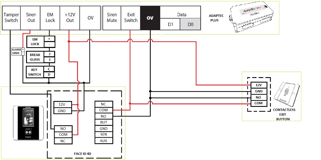
Setup External Siren
Requirements
· External siren 12VDC
· Power Supply AdapTec Plus
· Face ID 4D reader
· Switch (siren mute)
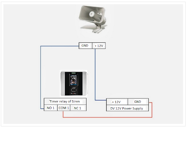
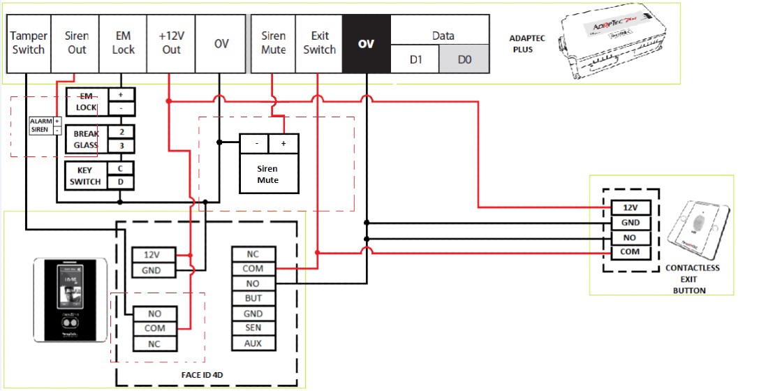
Wiring diagram
- Follow the diagram above for a wiring connection to install an external siren.
Please also make sure to connect the siren mute switch to stop the external siren.
- If you are using a 240vac external siren. You need to add relay connect with NO/COM from the device.
How to Setup Siren from Device
· Go to Main Menu – Select Personalize – go to Bell Schedules – choose Options – click External Bell Relay – tick on NC2
· Please make sure if you set Bell Schedule, don’t forget to change Repeat = ‘Never’ to the day you want to set the Schedule Bell.
Note: If some of the screenshots or steps viewed here are different from the ones in the current system, this is due to our continuous effort to improve our system from time to time. Please notify us at
[email protected], we will update it as soon as possible.
Introduction
In early 2020, FingerTec launched a brand-new platform for Face ID 4 series which is known as the FMM220. With higher capacity and higher performance, this new platform aims to help users gain better user experience.
User interface of the new Face ID 4D is different in comparison to the previous Face ID 4D. For those who need to utilize the external bell, especially in an industrial working environment, this article will provide you with the steps to configure the external schedule bell.
Wiring Connection
Attached is the wiring diagram of connection between the external siren and the Face ID 4D device.
The port connects with an external siren.
.png)
Configuration in device
1. Go to Menu > Personalize > Bell Schedule.
2. To enable the external bell function, users are required to select the correct bell type (either external bell or internal & external bell). 3. Please do not forget to set the external bell relay. Select NC2 to enable an external bell. .png)
You are all set to utilize the external schedule bell function after following the steps given above. If you are facing any issue regarding the setup, please do not hesitate to send your query to [email protected]
Note: If some of the screenshots or steps viewed here are different from the ones in the current system, this is due to our continuous effort to improve our system from time to time. Please notify us at [email protected], we will update it as soon as possible.
Introduction
WIFI connection is widely used these days to connect users with the most recent technology and updates. It provides users with greater mobility where the user can connect to a network or the Internet while moving freely around the space. For organizations that select the best mobile connectivity options, the choice often comes down to a WIFI connection.
At FingerTec, we offer a variety of selections of WIFI devices to meet the customer’s needs. Among the devices which FingerTec supports through the WIFI are Face ID 4 and Face ID 4D FMM220.
Basically, customers can have an option to purchase the Face ID 4 and Face ID 4D FMM220 with or without the WIFI function. For customers that have already bought the Face ID 4 or Face ID 4D FMM220 that comes without the support of the WIFI function, here are the tips you need to carry out the WIFI Modification, if necessary.
Face ID 4 and Face ID 4D FMM220 WIFI Modification requires the WIFI Module and the WIFI Antenna. If you need to perform the customization, you may send us an inquiry to www.fingetec.com or call our reseller for further assistance.
Steps
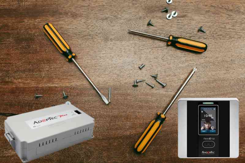
1) Unscrew the back cover and open it. Please be careful when you are disconnecting the speaker cable. The speaker is located at the back cover whereas the connector is located at the MCU. 2) Disconnect RLED cable, RFID cable, USB cable, GND and Touch panel flex cable from the MCU
3) Take out the MCU by slightly pushing forward the cover clip from MCU and pull it out from the MCU.
4) Separate the LCD Screen from the MCU by slightly pushing the LCD screen bracket clip and carefully pull up the LCD screen bracket from the MCU. There you will find a LCD Flex cable connects to the MCU and that needs to be disconnect by slightly pulling the black clip toward the Flex cable (Please do not fully pull out the clip. Ensure the cable is just about loose from the connector) and then you may pull the cable out cautiously.
5) Solder the WIFI Module on the MCU and connect the WIFI Antenna at the WIFI Module
6) Reverse step for the installation for MCU by connecting all back and peel of the WiFI Antenna sticker and stick on the front cover before closing it with the back cover
8) Configure Face ID 4 or Face ID 4D to connect it with WIFI
Menu > COMM > Wireless Network > WIFI (ON) > choose WIFI that want to be connected
Note: If some of the screenshots or steps viewed here are different from the ones in the current system, this is due to our continuous effort to improve our system from time to time. Please notify us at [email protected], we will update it as soon as possible.
Introduction
FingerTec’s Face
ID 4d Terminal can be customized to support External Schedule which is useful
in alerting employees to change shift or clocking status. However, take note that upon enabling this option, the
Door Access feature of this device will be disabled.
Benefits
By
using the external bell function, you can increase the volume of the alert bell
so it can be heard from a distance. This is suitable for industrial working
environment, such as factories.
Process
1. Update the firmware of the device.
You can download the customized firmware from here.
**Note: By updating this firmware, Door Access feature of
this device will be disabled
- Run the FTFaceID4.exe > Insert
Device’s IP Address > Connect > Update > Restart
2.
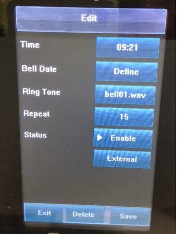
Set the Schedule Bell on Face ID 4D, select External.
Go to Menu > Date/Time > Bell >
Select Schedule Bell >
Insert your bell trigger date and time followed by the trigger period.
3.
Connect the device to the external siren as shown in the wiring
diagram below:
And you are ready
to test it! Make sure you are not too close to the siren to avoid damage to
your ears.
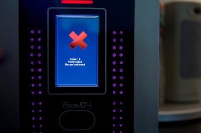
FingerTec has developed a new, added safety feature for Face ID 3 and Face ID 4/4d! When a face template fails to be identified by a terminal after a certain period of time, a photo of the face will be captured and stored. Below are some sample screenshots for a failed verification:
 |
| Failed verification in Face ID 3 |
 |
| Failed verification in Face ID 4 |
This is useful as administrators can trace back and determine the failure frequency of a particular individual by using FingerTec's TCMS V2 software.
The fail time period of each terminal is set to 10s by default. However, the time period is adjustable. To do so, simply follow the steps below:
Menu > System > Log Settings > Face Fail Time > Enter desired
duration
At
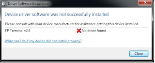
the moment, the Windows OS does not recognize the Face ID 4 device when you connect it
to the computer using USB/Client connection.
You will need to install the USB driver
manually if you wish to connect the Face ID 4 device to the computer using USB/Client
connection.
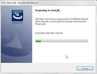
2- To install the USB client
driver:
i-
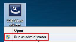
Right click at the .exe file and select Run as administrator.
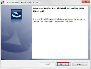
ii-
Click Next.
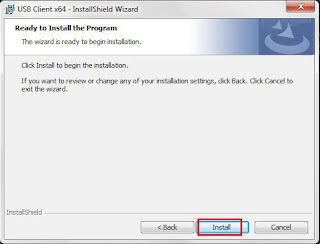
iii-
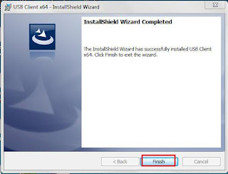
Click Install.
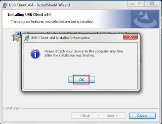
iv-
Click OK and Finish.
3- Plug in the USB client to
the PC and it will install the device driver automatically.
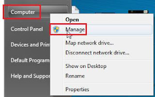
4- Right-click at Computer and select Manage.
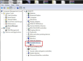
5- The Face ID 4 device is now detected under Portable Devices in Device Manager.
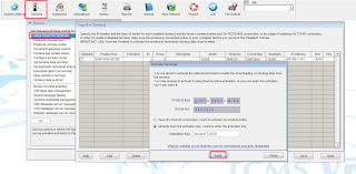
6- Finally, perform the terminal activation
in the TCMS V2 software.
Initiated and written by: Ery




.png)
.png)
.png)
4.png)
.png)
.png)
.png)


1.png)
1.png)
1.png)
1.png)
1.png)
2.png)
2.png)
2.png)
3.png)
2.png)

