Introduction
Ingressus controllers are designed to control access for a one-door (Ingressus I), two-door (Ingressus II) and four-door environment (Ingressus IV). With Ingressus, a user needs to verify his identity at a Wiegand terminal or an RS485 reader with fingerprint, card, password or any combination of credentials during entry and exit. The Ingressus has to finalize the user’s identity before granting him access to a particular area. The transaction records will be saved into the Ingressus’s inbuilt memory and sent to the software for further processing. Multiple Ingressus installations can be centralized via IP or RS485 connection in a computer installed with the bundled Ingress software. Each Ingressus I works independently at its access point; however, the data is centralized from all Ingressus controllers to give a better and complete picture of the entire security level.
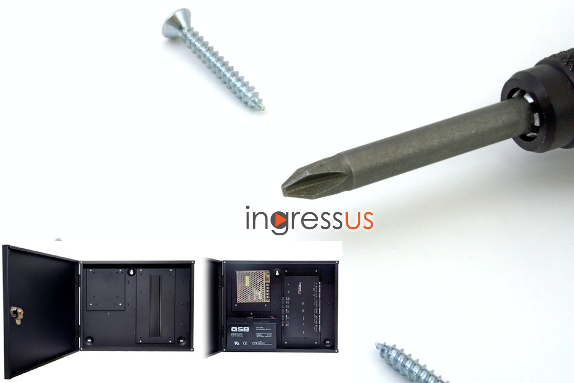
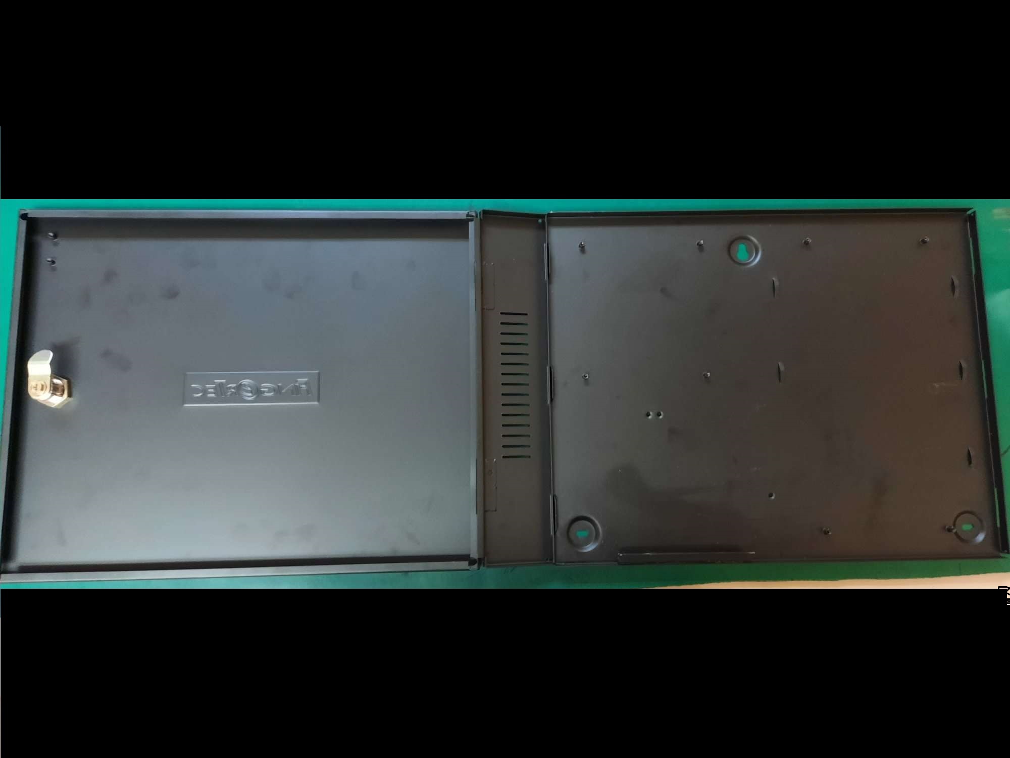
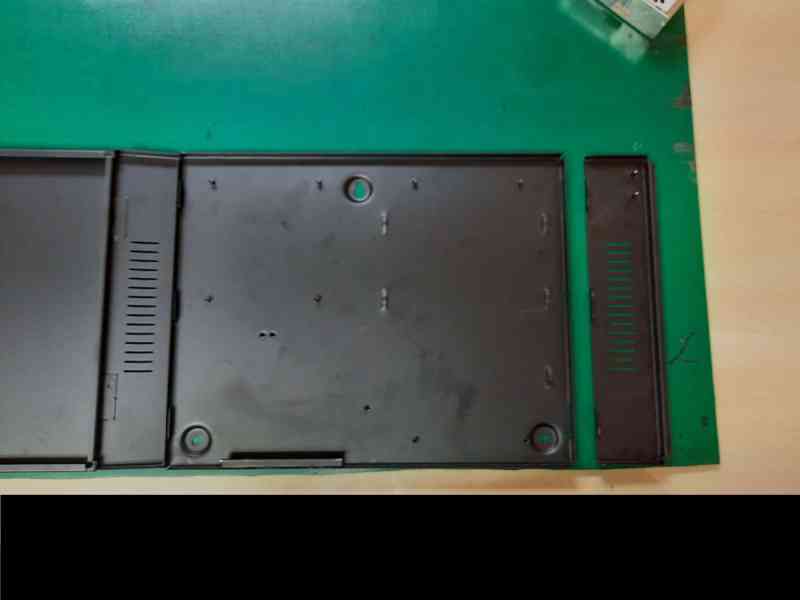
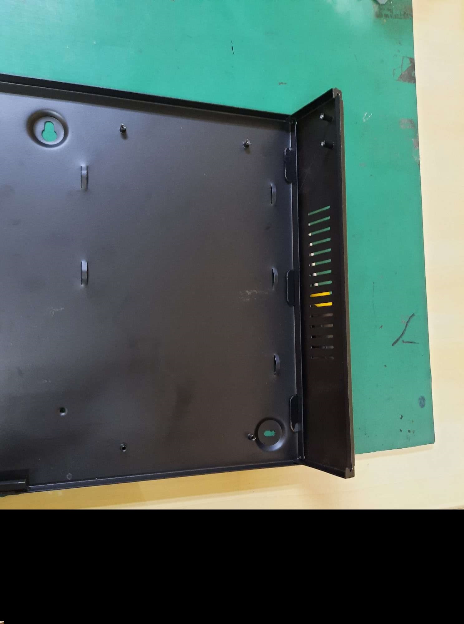
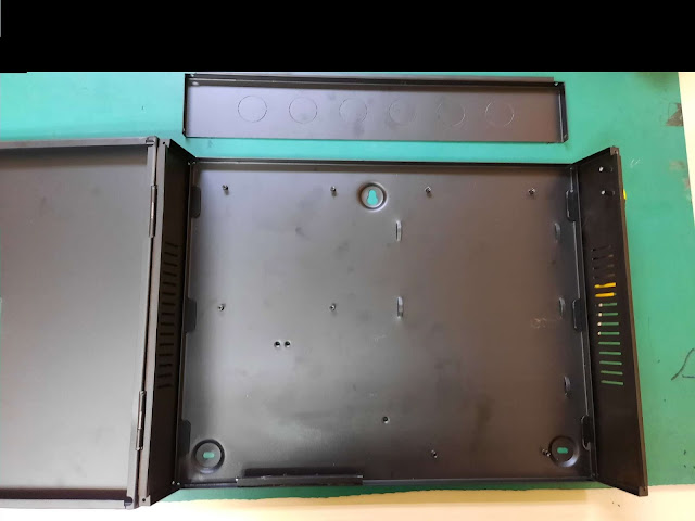
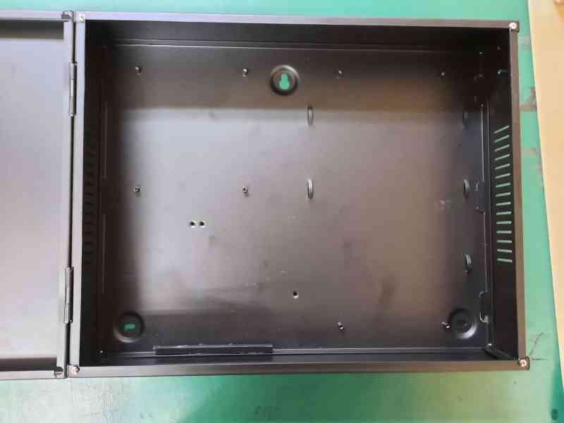
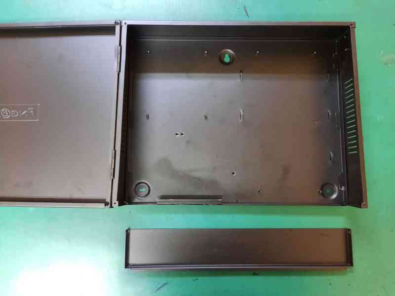
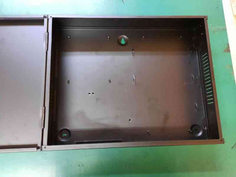
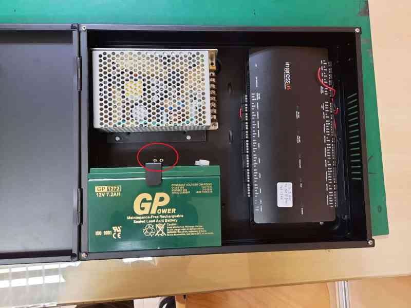
To set up the Ingressus controller, a 12VDC power supply and backup battery are needed to operate and function well as access control. As these components are needed, the Metal casing is essential to place these components for better maintenance and safety. Therefore, FingerTec provides a specific metal casing accessory for the Ingressus Controller to ease installation. Here are steps for Ingressus metal casing setup:
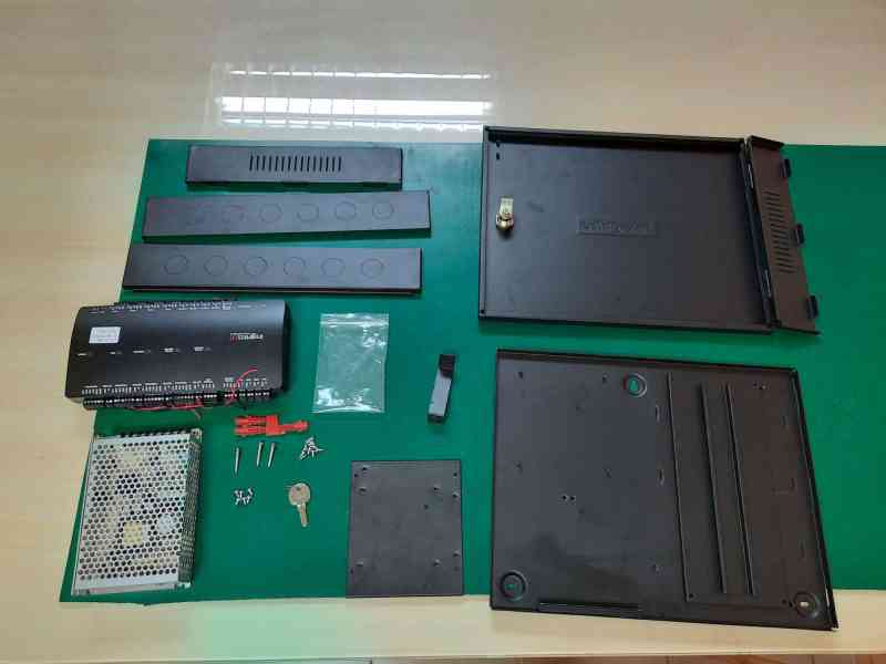 Ingressus Metal Casing Set
Step 1 : Join the back and the front metal casing
Step 2: Join the right side of the metal casing
Step 3 : Join the top metal casing
Step 4 : Join the bottom metal casing
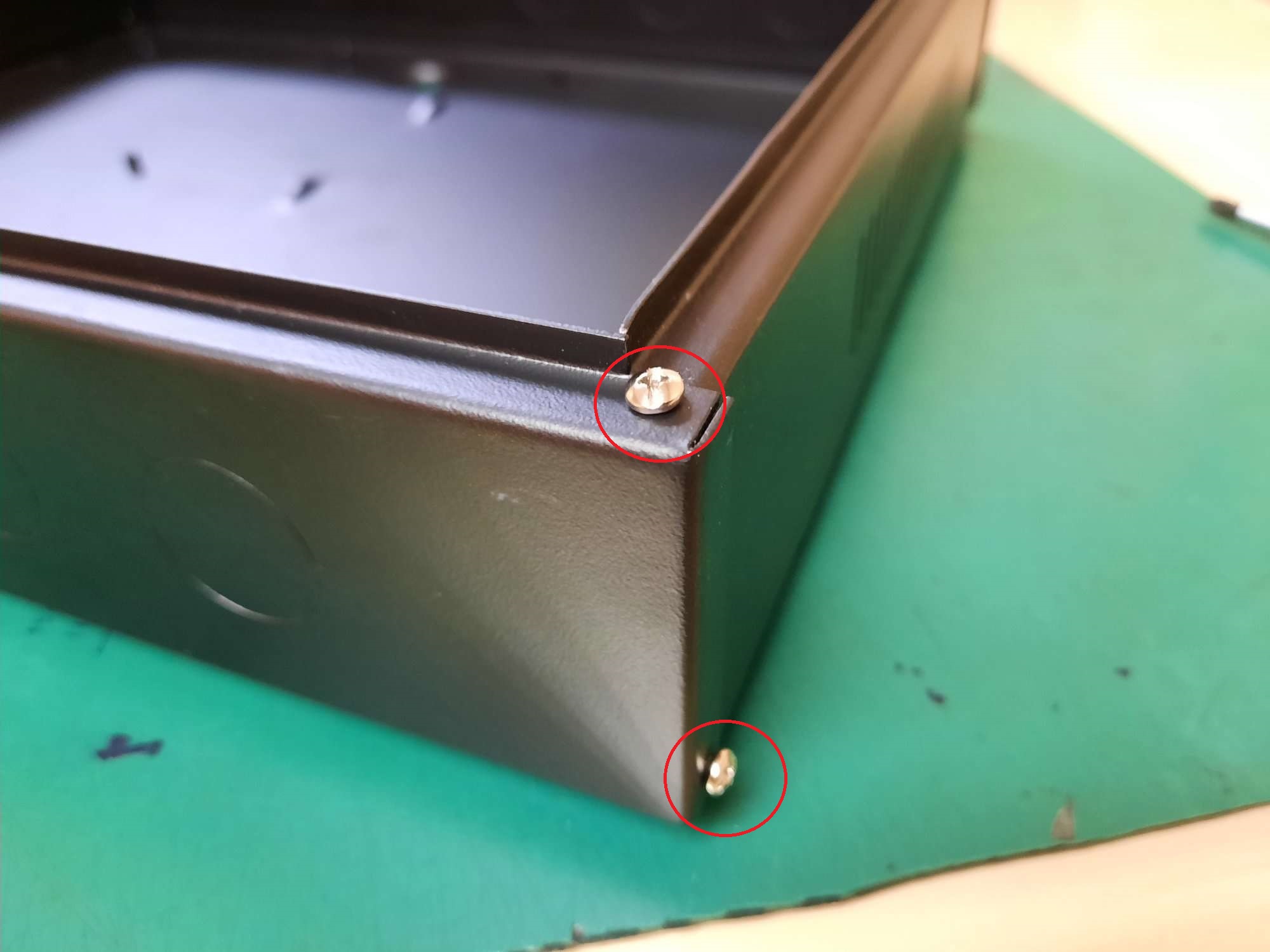
Step 5 : Prepare the 8 casing Screws
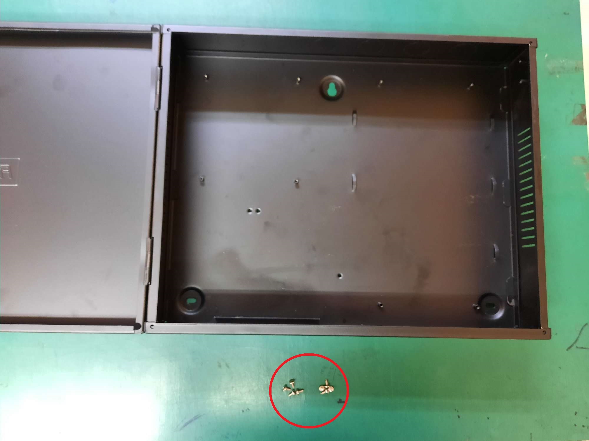
Step 6 : Screw every corner of the metal casing
Step 7 : Prepare 4 holder screws
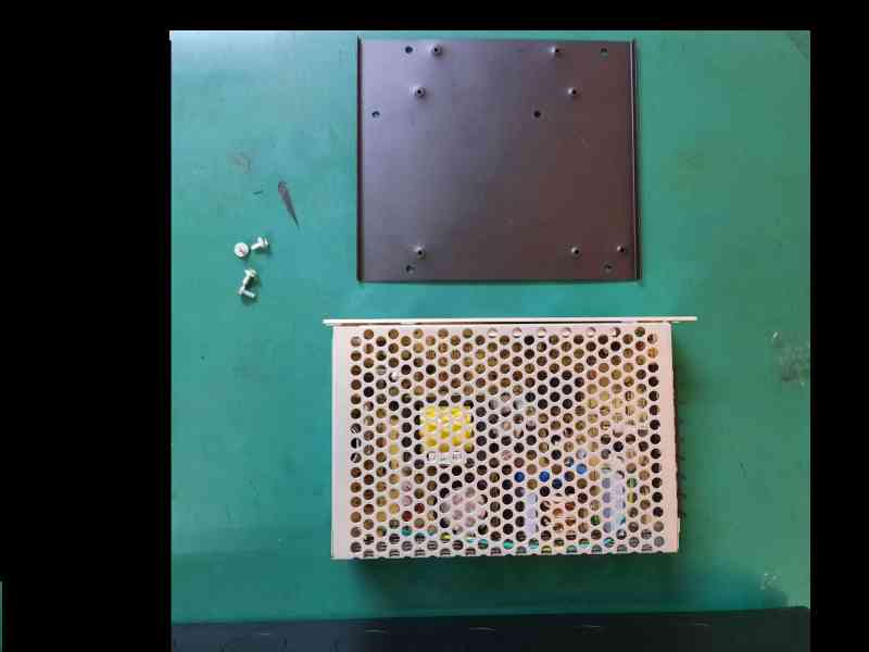
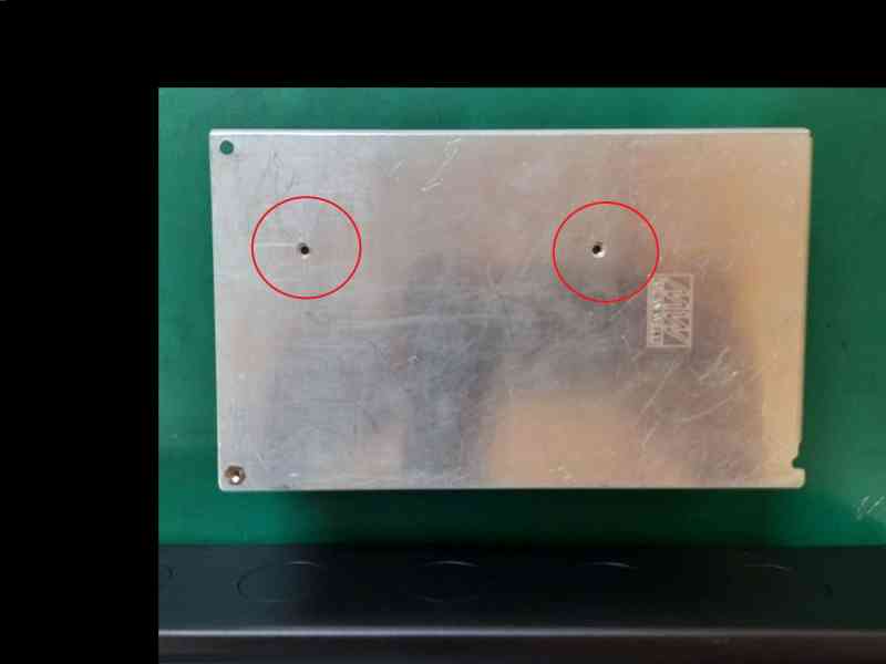
Step 8 : Flip the power supply
Step 9 : Align the bracket with the power supply, screw hole and screw it with 2 Holder screws
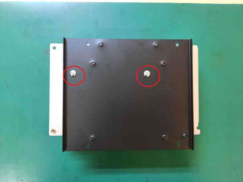
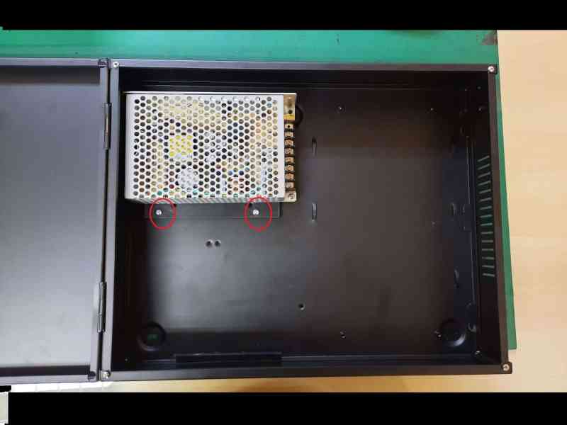
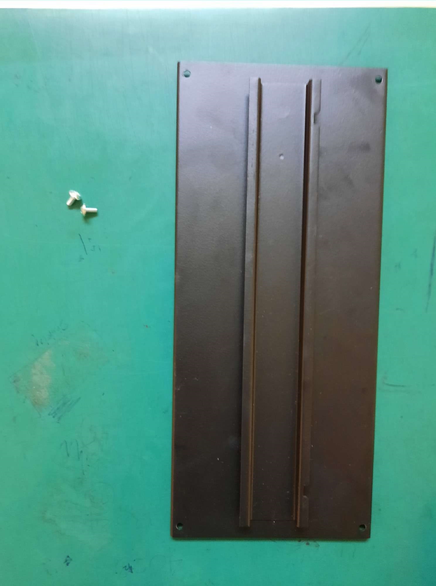
Step 10 : Screw the bracket to metal casing with 2 holder screws
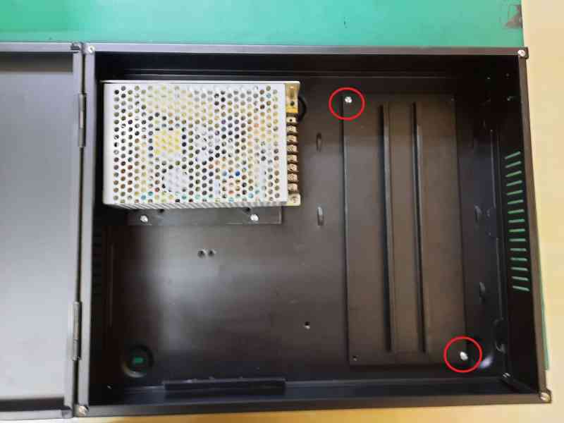
Step 11 : Prepare 2 Holder screws
Step 12 : Screw Bracket at the metal casing with 2 Holder screws
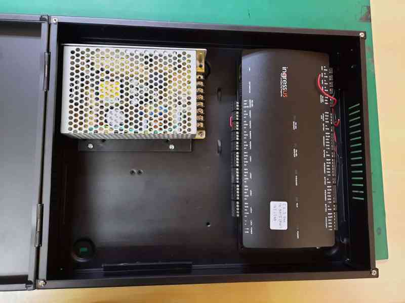
Step 13 : Slot in the ingressus at the bracket where Ingressus have DIN Rail slot at the back
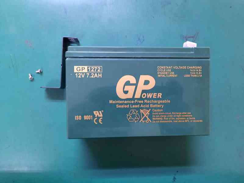
Step 14 : Prepare 2 Casing screws
Step 15 : Mount battery with Z bracket by screwing it with the Casing screw
Note: If some of the screenshots or steps viewed here are different from the ones in the current system, this is due to our continuous effort to improve our system from time to time. Please notify us at [email protected], we will update it as soon as possible.
Introduction
For higher-level security, interlocking is the fundamental parts of door access security where two doors are interconnecting, where each of the doors must entirely close before one could access another door. This feature is to prevent someone from tailgating authorized personnel and entering the room without permission.
Interlocking is available in Ingressus II and Ingressus IV controller because it involved the installation of at least two doors.
Requirements
- Ingress software
- Ingressus II or Ingressus IV controller
- Slave reader connected to Ingressus controller
- Door sensor installed at the door
Ingress software must be connected to Ingressus controller while each door must be installed with the door sensor to monitor the door open-close activities.
How to activate interlocking?
Steps
Select ‘DEVICE’ -> click ‘Zones’ -> select ‘Interlocking’ -> click ‘ADD ZONE’ -> rename interlocking zone
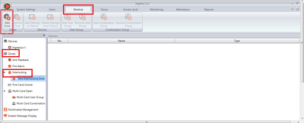
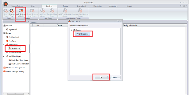
Select interlocking zone “Server room” -> click ‘ADD SETTING TO DEVICE’ -> select check box for the selected device -> click ‘OK’
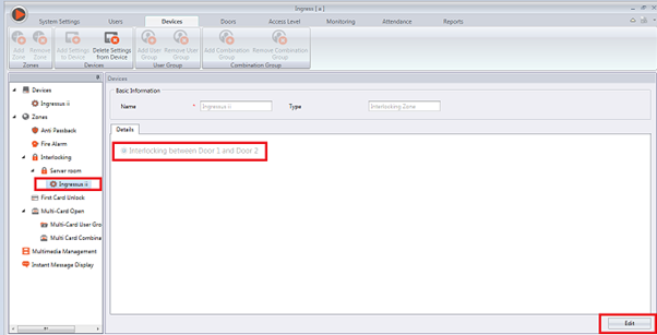
Select device “Ingressus ii“ -> Click ‘EDIT’ -> Select ‘INTERLOCKING BETWEEN DOOR 1 AND DOOR 2’ -> ‘SAVE’
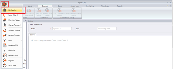
Synchronize software with controller -> Click on Icon Ingress -> Select ‘NOTIFICATION’
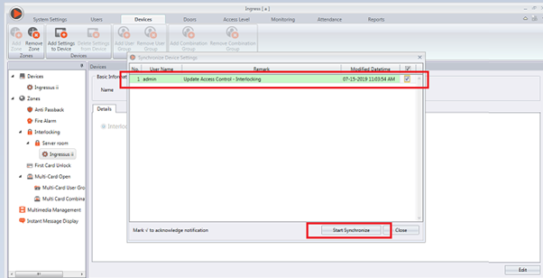
Click check box -> ‘START SYNCHRONIZE’ -> click start synchronize again
How Does It Work?
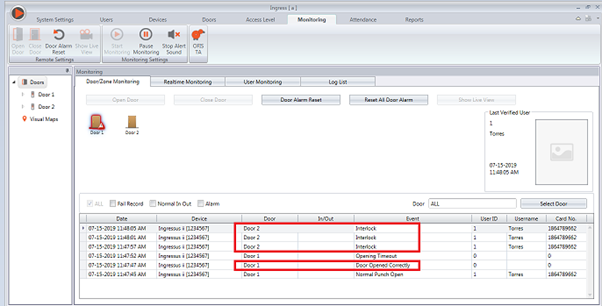
Access the first door. If you try to open the second door without closing the first door, you can see the ‘Interlock’ sign appears.
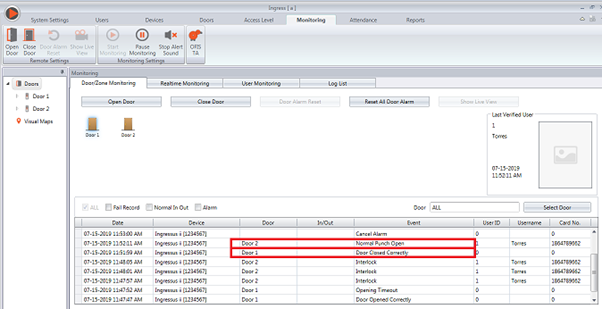
You can only access the second door when you close the first door properly.
Note: If some of the screenshots or steps viewed here are different from the ones in the current system, this is due to our continuous effort to improve our system from time to time. Please notify us at [email protected], we will update it as soon as possible.
Introduction:
FingerTec Ingressus I,II and IV devices have the capability to support all doors in opening and closing them when the alarm is triggered in case of an emergency such as a fire.
Basically, Ingressus has an auxiliary input that can be configured via Ingress software. This input is a dry contact (disconnected) and has no voltage supply.
By using this input, users can send a signal to Ingressus in case of fire hazards occuring within the building. You will however, still need to utilize a smoke detector or third party fire alarm system that can send signal to the alarm using a dry contact signal.
Scenario:
i) The main idea below is how to keep the doors opened during a fire emergency. Please find below details for Ingressus specification that you need to know in order to set up for fire alarm system.
1. Ingressus 1
(one aux-in / one aux-out) to control two doors during a fire alarm.
2. Ingressus 2
(two aux-in / two aux-out) to control four doors during a fire alarm.
3. Ingressus 4
(two aux-in / two aux-out) to control six doors during a fire alarm.
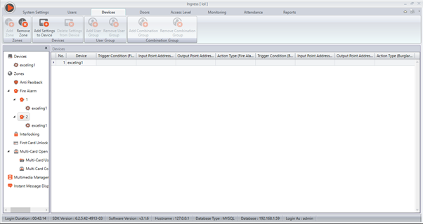
As for Ingress software, there are still some configurations that need to be carried out. Please refer to the screenshot below:
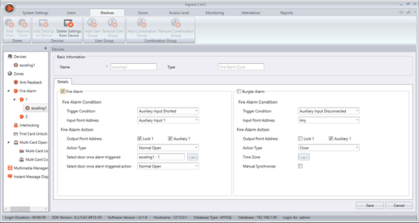
Firstly, please set the Fire Alarm Condition to Auxiliary Input 1 and the Trigger Condition to Auxiliary Input Shorted. This is so that the Ingressus will receive the signal from the fire alarm through Auxiliary Input 1. Next, check both Lock 1 and Auxiliary 1 at Output Point Address as well as select the Action Type as Normal Open.
In doing so, when the fire alarm triggers, it will shorten the Auxiliary Input 1 and cause the door to open (Auxiliary Output 1). Normal Open condition will thus keep the door opened until it is manually closed at Ingress software.
ii) Close door automatically after the alarm goes off.
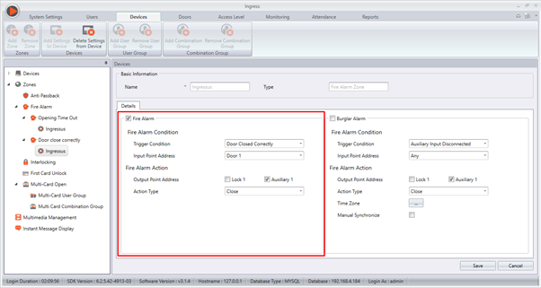
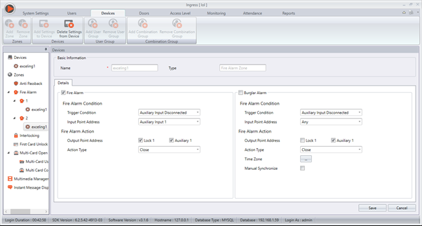
As shown in the screenshot below, please set the Fire Alarm Condition to Auxiliary Input Disconnected and Input Point Address to Auxiliary Input 1 as well as the Action Type to Close.
Once the fire hazard has been dealt with, the fire alarm will usually revert back to normal condition and stop the alarm. In this case, it will disconnect the Auxiliary Input 1 and close your door.
Configuration in Ingress software:
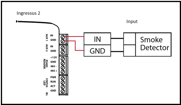
 Wiring Diagram for further reference:
Input
 - (can be any dry contact signal)
(Diagram 1)
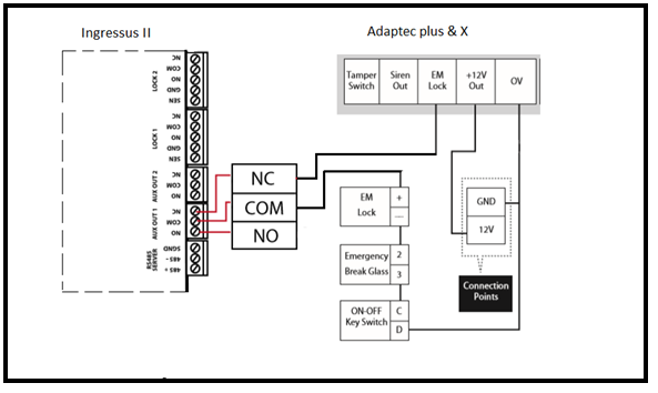
Output - (Adaptec Plus / X)
(Diagram 2)
As you can see in Diagram 2, your door should be connected in series with the Ingressus Auxiliary Output. Therefore, when the Ingressus Auxiliary Input is shorted, it will open the Auxiliary Output which will in turn open the EM Lock circuit.
Standalone device:
(Diagram 3)
Diagram 3 shows that the door is connected in series with the NC/Com of Ingressus door. Hence, when the input is triggered, Ingressus Auxiliary Input will be shorted and unlock the Ingressus door as well as the EM Lock circuit. Please however, DO NOT USE a single Auxiliary Output for two doors as it will affect your voltage supply for the EM Lock.
Note: If some of the screenshots or steps viewed here are different from the ones in the current
system, this is due to our continuous effort to improve our system from time to time. Please notify us at
[email protected], we will update it as soon as possible.
 INTRODUCTION
To increase your security while using Ingressus controller in controlling the doors, you can configure it via Ingress Software to trigger an alarm if the door stays ajar for a specific time, say for example 10 second. Therefore, if the door is left open for 10 second without closing, the system will trigger an alarm to alert people. To setup this feature, please follow the simple steps below:
PROCESS -
Go to the Devices tab > select Zones > select Fire Alarm > add new Zone > add setting to device > select device > select the Trigger Condition to “Opening Timeout”. Refer to the screenshots below for more information.
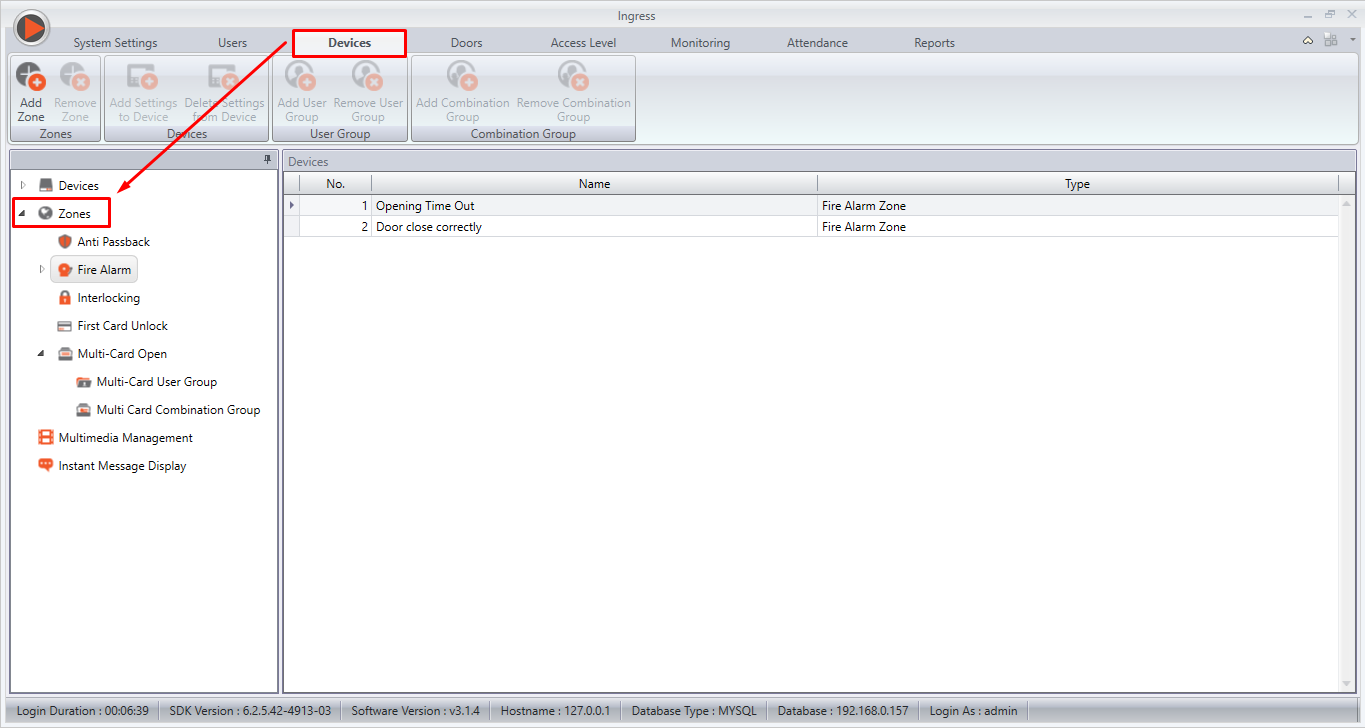
(Figure 1)
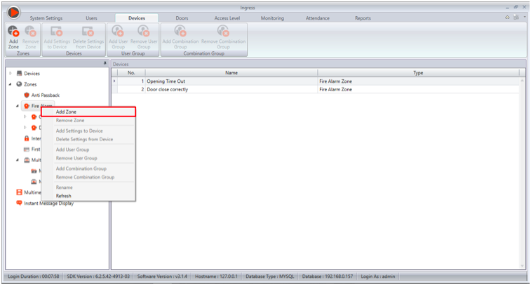
(Figure 2)
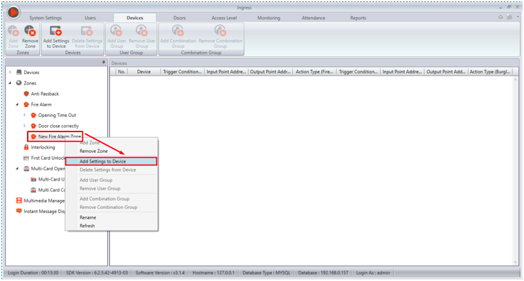
(Figure 3)
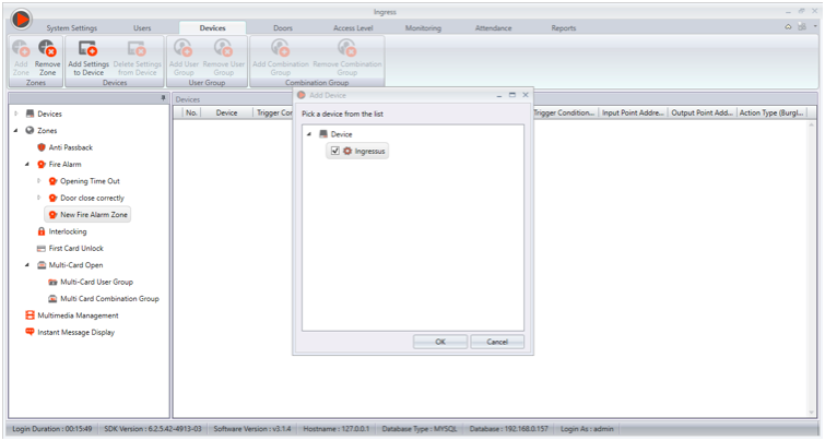
(Figure 4)
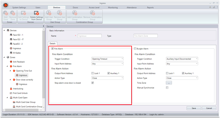
(Figure 5)
For the last option, which is “Stop alarm once door is closed”, please tick it so that if the door is closed, Ingressus will deactivate the alarm automatically. However, this option will only take effect if Ingressus is connected to the Ingress server.
If the controller is not connected to the Ingress server, you have 2 options to deactivate the alarm:
1) Restart the controller.
2) Configure the settings from Ingress and upload it to the controller.
For the second option, please follow the steps below:
Go to the Devices tab > select Zone > select Fire alarm > add new Zone > add setting to device > select device > select the Trigger Condition to “Door Closed Correctly”. Refer to the screenshots below for more information.
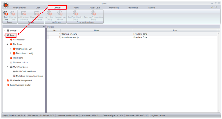
(Figure 1)

(Figure 2)

(Figure 3)

(Figure 4)
(Figure 5)
For the best configuration, please upload both settings discussed above in order for your controller to work perfectly regardless whether the Ingressus controller is connected or not connected to the Ingress server.
Once completed, the display should have 2 options under the fire alarm zone as shown in the image below.
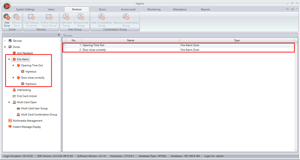
That’s it, you’re all set and you can now utilize this alarm feature to increase your office security.
 Ingressus Metal Casing Set










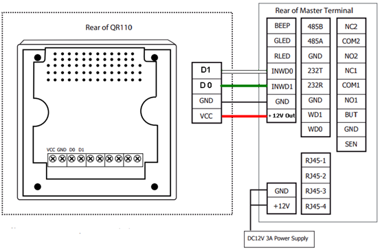
 Introduction On Vehicle Access Control:
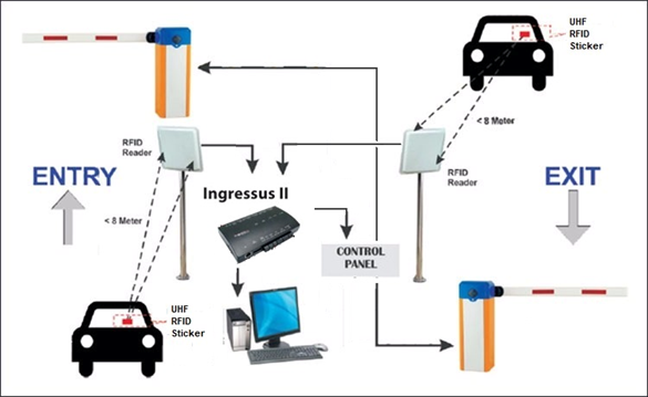
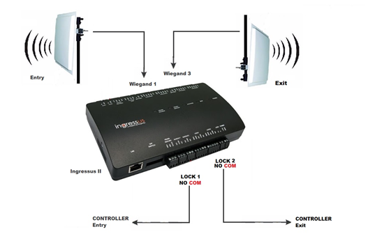
 Introduction:
 INTRODUCTION
 (Figure 1)
 (Figure 2)
 (Figure 3)
 (Figure 4)
 (Figure 5)
 (Figure 1)