Introduction:
Turnstile is a form of gate which provides access to an individual at a time. It also can be utilized as a way to enforce a one-way traffic for the community in addition to restricting passage to only authorized individuals.
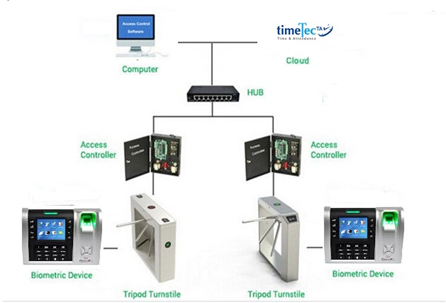
In this article, we will show you the installation diagram for FingerTec Q2i reader with the turnstile. Note in our setup: apart from using Ingress software for the access control and attendance software, we also will be applying our new TimeTec TA application as the cloud storage system to store the user and transaction data into cloud.
Following the setup, users can thus use TimeTec TA to view the data at any time from any place by computers or through their smartphones.
Q2i Terminal on Turnstile with Software and TimeTec TA
This setup is suitable for the lobby at an office building. With this setting in placed, it will allow access to authorized individuals only; while at the same time, preventing strangers from tailgating into the premise.
Wiring & Installation Diagram:
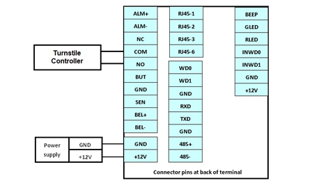
At the back of FingerTec Q2i device; note that the NO and COM connector from the Q2i device needs to be connected to the Turnstile Controller as shown in the image below.
Connector Pin at the back of FingerTec Q2i
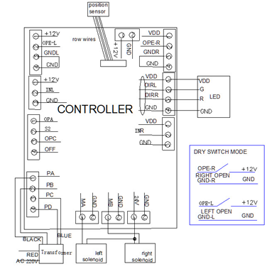
For example, below is a Controller Diagram from a Turnstile that is available in the market. As such, please connect the NO and Com connectors at Q2i Terminal to:
i. OPE-R and GND-R (respectively) to turn on the Right Solenoid
ii. OPE-L and GND-L (respectively) to turn on the Left Solenoid.
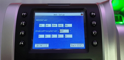
Additionally, to use TimeTec TA App and Web Application in the setup, users will need to key in TimeTec TA IP address into the terminal by proceeding to the Menu > Comm > Web Setup.
Key in TimeTec TA IP address at FingerTec Q2i
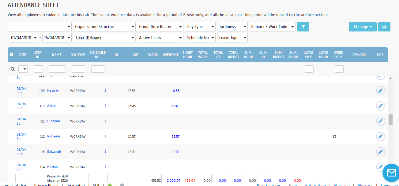
Once done, the transaction record will be displayed in TimeTec TA as shown in the example below:
Note: If some of the screenshots or steps viewed here are different from the ones in the current
system, this is due to our continuous effort to improve our system from time to time. Please notify us at
[email protected], we will update it as soon as possible.
Introduction
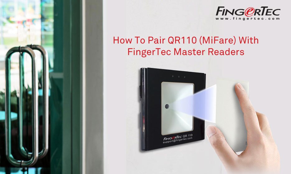
FingerTec QR110 is a slave QR code reader for door access, and recently this model has been designed to also read MiFare card. This is a quick guide on how to pair QR110 (MiFare) with FingerTec Master Readers.
For information on QR110 (RFID) please refer to this post:
How to pair FingerTec QR110 Slave Reader with FingerTec Master Readers
QR110 (MiFare) Compatible Device -
Below are the list of FingerTec device models that are compatible with QR110 (MiFare):
1. R2
2. R3
3. Q2i (FEM 800 only)
4. Kadex
5. M-Kadex
6. Ingressus Controller
Note that QR110 (MiFare) is using 34-bit Wiegand signal to communicate with the master readers.
Requirement -
The main requirements needed for pairing QR110 (MiFare) with the master readers are:
1. Wiegand-In Port
2. Wiegand 34-bit Communication
3. MiFare Card
Connection between QR110 and FingerTec Master Readers -
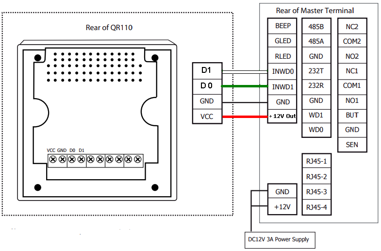
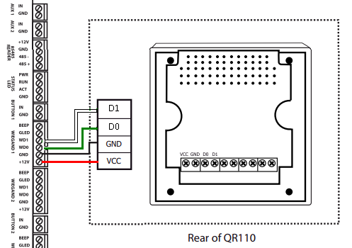
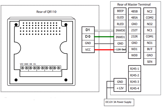
The connection for QR110 (MiFare) with the Master Readers is the same with QR110 (RFID). You may find the connection details as shown in the diagram below:
1. Pairing With Ingressus Controller
2. Pairing With FingerTec Master Readers.
QR110 MiFare Setting -
As QR110 MiFare reader is a very simple and convenient reader to begin with, no configuration or setting is required from the device. All users need to do is just plug in the device and the process is complete.
Master Readers Setting -
Before pairing the Master Readers with QR110, the devices on the other hand, will first need to be enabled in Wiegand 34-bit format as per the setting below:
1. R2 and Kadex:
Menu > option > system option > Wiegand input setting > FP device > Input format = WG34 Without ID > Restart.
2. R3 and Q2i:
Menu > Comm > Wiegand > input option > Define = 34 > Bit counts = 34 > Input = NO. > Restart.
3. Face ID 3:
Menu > comm > Wiegand input > Wiegand Format = Wiegand 34 > Input = Card No. > Save > Restart.
4. m-Kadex:
Requires a tool update as provided below (also works with R2 and Kadex):
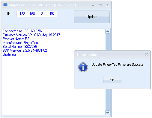
https://s3.amazonaws.com/files.fingertec.com/Azim+Tools/Tools/FTEnableWG34_BWdevice.exe
5. Ingressus:
Connect 3 Wiegand cables between QR110 (MiFare) reader and Ingressus (no other settings required).
Once done, FingerTec Master Readers will thus be paired up with the QR110 (MiFare) reader.
Note: If some of the screenshots or steps viewed here are different from the ones in the current system, this is due to our continuous effort to improve our system from time to time. Please notify us at [email protected], we will update it as soon as possible.
Introduction:
FingerTec has updated Q2i FEM800 firmware which now includes an enhancement on Permanent Door Open feature to provide more flexibility in terms of scheduling door opening.
Benefits:
Permanent Door Open Close Time Zone feature in Ingress allows you to set the unlocking option for your doors with up to 3 different intervals daily. This feature is usually used in Service Centre whereby the front door is often kept unlocked for customer access without the need for staffs to unlock the door. Previous firmware of Q2i is only able to support 1 interval and with this firmware update, the system can now support up to 3 intervals.
Process:
For the Service Centre front door, it should remain open during working hours and close during lunch time. Hence, there are two time-interval to be included for this situation. Considering that the device is using normally close door, the two time zone intervals are:
1) (0800 – 1200) – First Work Period: Door will automatically unlock at 8 am and lock at 12 pm.
2) (1300 – 1700) – Second Work Period: Door will automatically unlock at 1 pm and unlock at 5 pm.
Steps in Ingress software:
1) Add new Time Zone
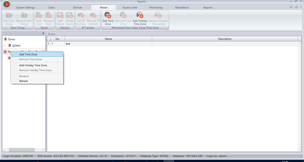
2) Set your interval as Permanent Door Open period.
In this situation, we need to include 2 intervals which are during First Work Period and Second Work Period.
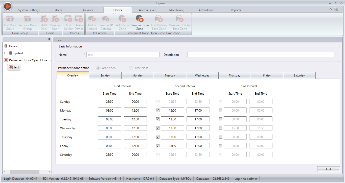
As Sunday and Saturday are rest day, the interval will remain (0000 – 2359) in order to ensure that the door is always lock.
3) Assign the Permanent Door Open Close to Your Doors
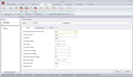
To change the settings of your door, click on your door name and click on Edit at “Details”.
4) At the Permanent Door Open Close Time Zone, click on the drop down list.
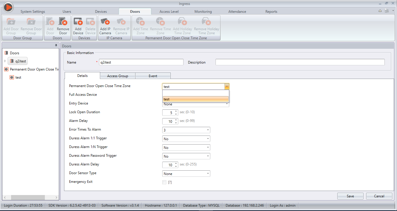
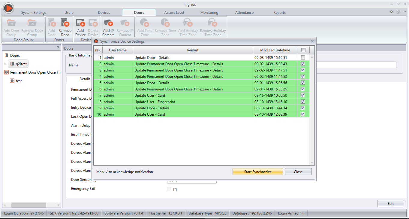
5) Synchronize the changes to the device (Q2i).
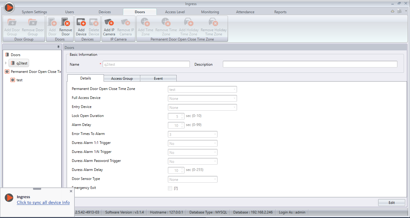
6) Sync and restart your device.
You can also refer to this /2016/05/the-flexibility-ingress-gives-your.html for more information about Ingress Permanent Door Open Close Feature.
FingerTec Authorized Reseller can now login and download the latest firmware of Q2i FEM800 at http://tips.fingertec.com/tips-download-firmware.php. For end users, please contact your local reseller or FingerTec Support Team to acquire this latest firmware update.
Note: If some of the screenshots or steps viewed here are different from the ones in the current system, this is due to our continuous effort to improve our system from time to time. Please notify us at [email protected], we will update it as soon as possible.
Introduction
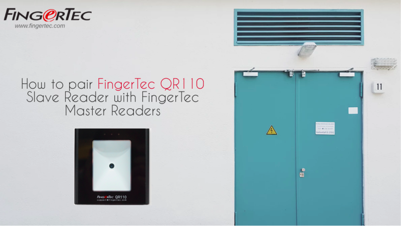
QR110 QR Code Scanner is FingerTec latest product that comes with a new verification method: QR Code along with the capabilities to scan RFID/MiFare access cards as well. As a slave reader, QR110 will need to be paired with FingerTec Ingressus controllers and master readers such as R3, R2, Q2i and etc before the whole system works.
Supported model:
Q2i, R3, R2, Face ID 3, Kadex, m-Kadex, Ingressus I/II/IV
QR110 is built with a 26-bit Wiegand communication. Even though FingerTec master devices comes with 34-bit and 26-bit Wiegand, by default all FingerTec Master Devices is set with 26-bit Wiegand Communication.
For information on QR110 (MiFare), please refer to this post:
How To Pair QR110 (MiFare) With FingerTec Master Readers
Please follow the steps below for QR110 (RFID) installation:
Process:
1) Connect the wirings between QR110 and FingerTec Controller and Biometrics Devices
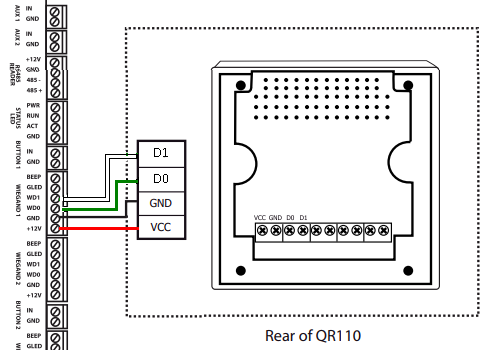
For Ingressus I,II, and IV, please connect the respective devices to the following QR110 ports (D1, D0, GND, VCC) as shown in the circuit diagram below:
QR 110 to Ingressus
For Master Readers (R2, R3, Kadex, m-Kadex, Q2i, Face ID 3), please connect the respective
devices to the following QR110 ports (D1, D0, GND, VCC) as shown in the circuit diagram below:
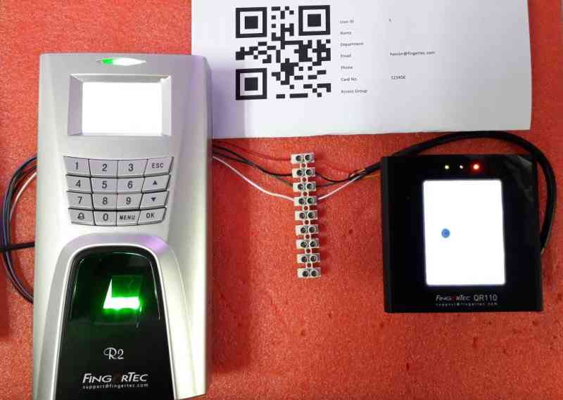
Example : R2 Connection to QR110
2) If there is no response on Master device when you wave card or scan QR code on QR110, please check the Wiegand bit Format in FingerTec Device
*QR110 is not compatible with Q2i (FEM 510)
and proceed to input the IP address of m-Kadex into the software tool. Once updated, the
m-Kadex device will now accept 26-bit Wiegand Connection. (This method can also be applied
to R2 and Kadex) Please refer to the screenshot below for more information:
In Ingressus I, II, and IV, the devices will automatically detect and configure its Wiegand Connection once connected to QR110. Therefore, removing the need for any manual setting.
After the configuration is done, the FingerTec devices will then be paired with QR110.
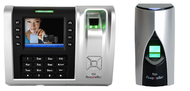
Effective immediately, Q2i
devices can now be paired with R2c readers. However, this is only possible for
Q2i devices with a core board that is version FEM800. When purchasing a brand
new Q2i terminal, remember to notify the sales person that the terminal is to
be paired with R2c as the slave reader.
If you are already using a
Q2i device at your place, please check the core board's version (either FEM600 or FEM800) before pairing it
with an R2c reader. You can check this info by using the FingerTec Device Info
tool. Read more for the step-by-step guide to enable the Q2i-R2c pairing.
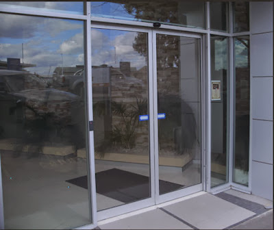
The automatic sliding door can be opened by activating control methods such as motion
detectors, push buttons, key switches and access control readers.
There
are three types of input that can be used by the automatic sliding door controller/motor
if you want to implement access control as the activating control method. Read more to see the three inputs.
The FingerTec 3G module is
ready to be used in models with FEM 800, which are TA200Plus (normal 12V
model), Q2i and Face ID 2. Refer to the below table for technical
specifications of the 3G module.
Technical Specifications
|
Frequencies
|
2G/2.5G –
GSM/GPRS/EDGE:
Frequency -
850/900/1800/1900 MHz
3G – UMTS/HSPA
Frequency –
850/1900/2100 MHz
3G – CDMA 2000
Frequency -
1900/2100 MHz
|
Communication
|
Full duplex
|
Automatic Startup
|
Yes
|
Antenna Impedance
|
50 Ohms
|
SIM Card
|
3 Volts (varies with SIM card)
|
SIM Card PIN
|
Only reads the SIM card PIN, but cannot amend
|
Receiver Parameters
|
GSM850 Reference Sensitivity
|
-104 dBm Static and TUHigh
|
E-GSM900 Reference Sensitivity
|
-104 dBm Static and TUHigh
|
DCS1800 Reference Sensitivity
|
-102 dBm Static and TUHigh
|
PCS1900 Reference Sensitivity
|
-102 dBm Static and TUHigh
|
Selectivity @ 200 kHz
|
> +9 dBc
|
Selectivity @ 400 kHz
|
> +41 dBc
|
Linear Dynamic Range
|
63 dB
|
Co-channel Rejection
|
>= 9 dBc
|
Test Results
In our test, the 3G module works almost 40% faster than its predecessor (GPRS module) and, more importantly, is more stable.
Read more for instructions on how to install the 3G modules.
With the launch of the Ingress software
just around the corner, FingerTec has released the Ingress Trial Version for
our resellers as well as end-users to test out the software before actually making a
purchase. The trial version is strictly accessible only to FingerTec’s
Authorized Resellers & Distributors and End-Users of FingerTec only.
The instructions below are intended to
help you understand the workflow, types of testing environment, and what you
need to prepare before you start the test.
Supported Models:
Multimedia Models:
AC100C, TA100C, TA100TC, TA200 Plus.
Access Control
& Time Attendance Models: Ingressus, Q2i, i-Kiosk 100 Plus, AC900, R2, H2i,
R2c.
Face Recognition
Models: Face ID 2, Face ID 3, Face ID 4, Face ID 4d.
Card Reader
Models: TimeLine 100, Kadex, m-Kadex, k-Kadex, i-Kadex.
Please make sure that the FingerTec
terminal you use for testing is listed above. Any terminals excluded from the list will not work with the Ingress Software. Next up, go to Ingress’s trial
version page to fill in the request form and submit it back to us. You are
required to insert your FingerTec terminal’s serial number for us to generate
the trial product key.
If you are not using a FingerTec terminal for testing,
you are still required to insert the testing terminal’s serial number,
and we will process it accordingly. If you do not have a terminal to test the
Ingress software, just leave the serial number text box empty and we will
provide you with an 8-digit device serial number and the trial product key. We
will email you once your Ingress trial application has been approved.
You can
access Ingress’s trial version page by clicking this link.
Once your application has been approved,
you may download the Ingress Trial Version software installer here.
Unzip the file, right click the
installation file and select Run as administrator to prompt the installation.
Follow the onscreen instructions to complete the installation.
Upon the Ingress installation, it is
mandatory to activate the device before you can use it to perform testing. There
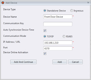
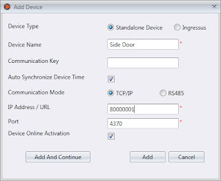
are 2 ways to activate the device. While adding new devices to the software, tick
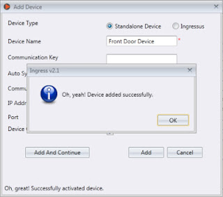
the checkbox for Device Online Activation.
Once the activation is completed, you
can see a “Successful Activation” message at the bottom left corner of the
window.
As mentioned above, if you do not have any
terminals to perform testing, please insert the given serial number at the IP
Address / URL text box and tick the checkbox for Device Online Activation. Click Add to
activate the serial number and then you may start to use the Ingress software
for testing.
Another way to activate the terminal is in Devices.
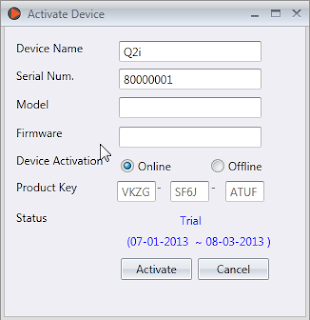
Click on the device that you want to activate and click Activate Device.
At the Activate Device window, there are 2
methods to activate the device; either Online or Offline. If you choose
to activate the device online, select Online and click Activate. The Ingress Software
will connect to our database server to verify and activate the device
accordingly. You will see the device’s activation status as well as the expiry
date.
If you choose to activate the device offline, kindly
contact us at [email protected] to request for the trial product key. Then insert
the given product key into the text box. Select Offline and click Activate to
proceed with the activation.
Written by Vincent
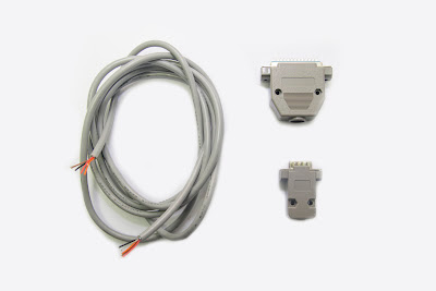
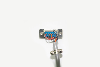
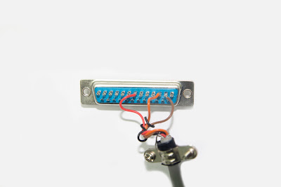
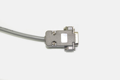
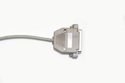
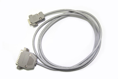
The original communication cable that comes with the EPSON Thermal Printer TM-T88IV is not compatible with the FingerTec terminals. A modification to the cable is required before you can use it with the FingerTec terminals.
Things to prepare:
1 X Male Serial
Socket (9 pins).
1 X Male Parallel
socket (25 pins).
1 X RS485 cable (1
meter).
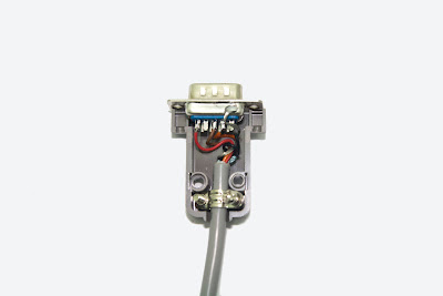
Step 1: Solder the wires at RS485 cable to the serial socket as shown
at the photo above.
Pin 2 – Orange, Pin 3 – Brown, Pin 5 - Red
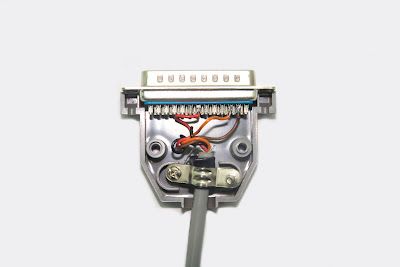
Step 2: Solder the wires at the other end of the RS485 cable to the
serial socket as shown at the photo above. Pin 2 – Brown, Pin 3 – Orange, Pin 7 – Red
Step 3: Place the soldered socket with the wires back to the casing.
Step 4: Screw and assemble the casing together.
Step 5: The printer cable is ready to be used.
Contributed By: SF Lim
Edited by: Vincent


.jpeg)


